Setup guide
Wiring the F405 Flight Controller
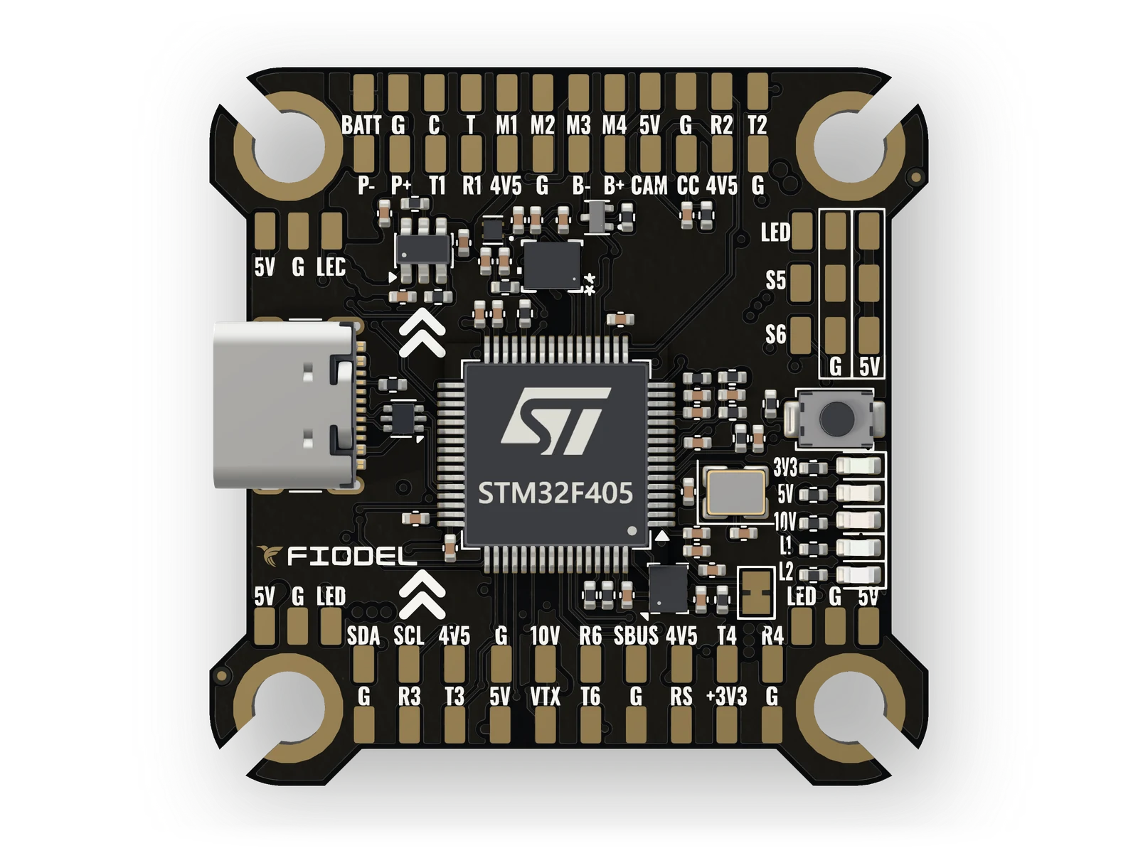
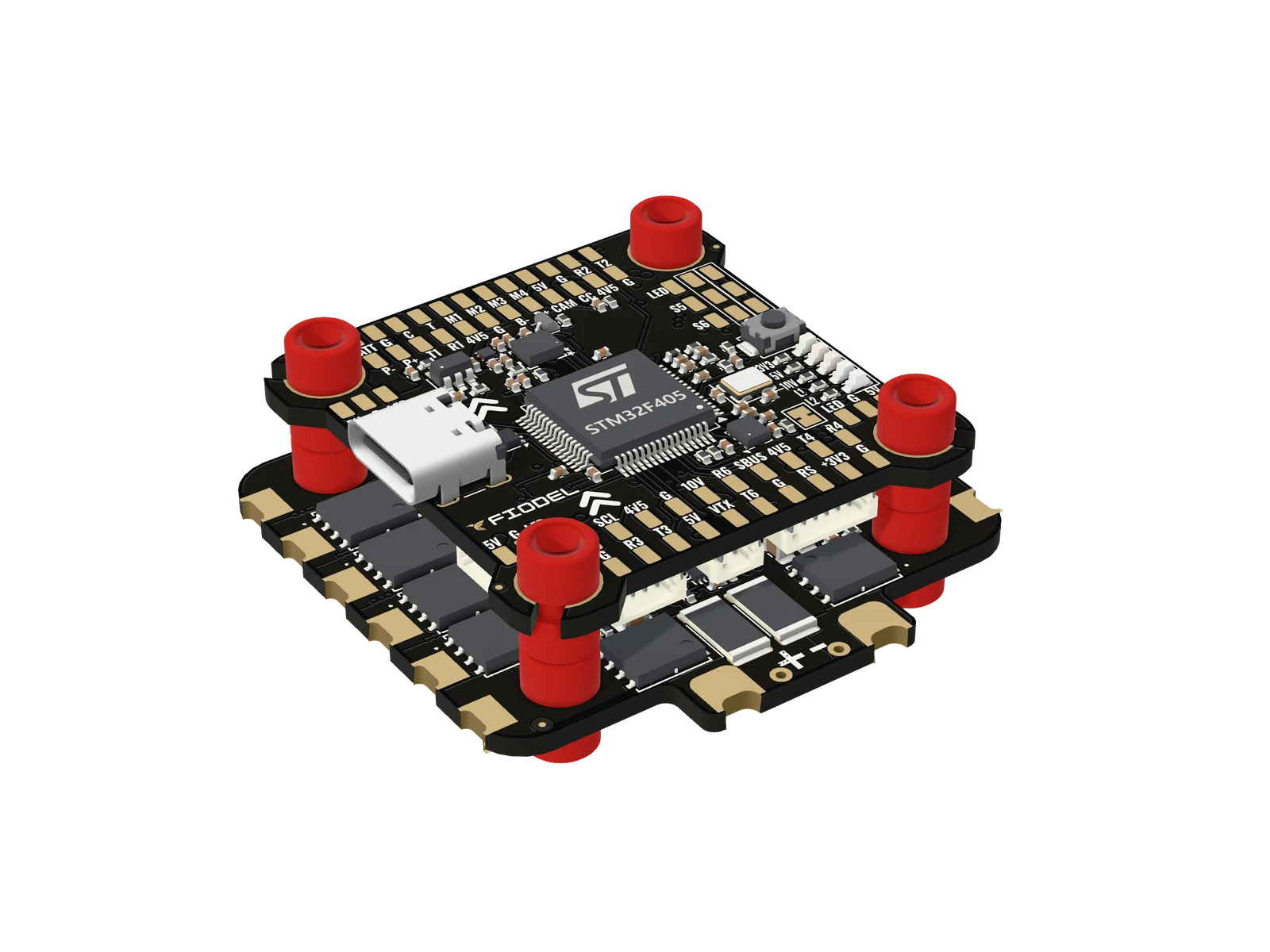
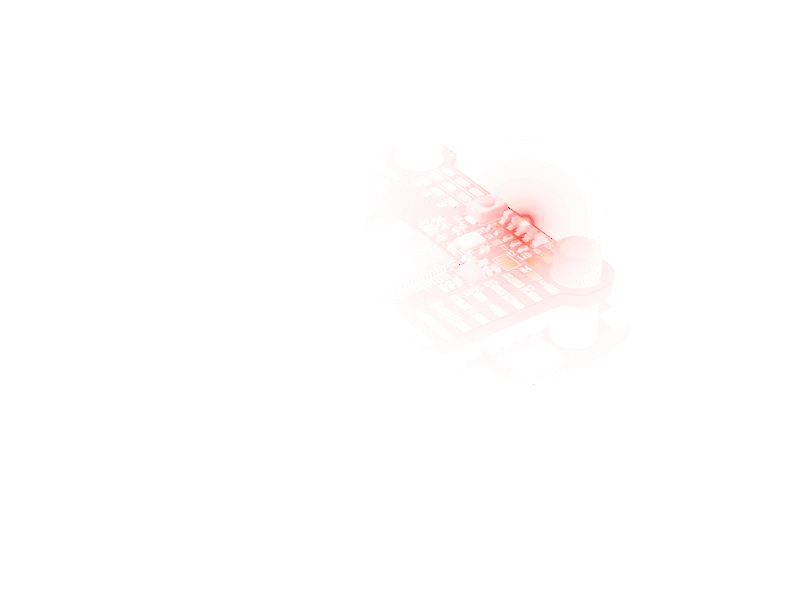
What plugs into which socket of the Fiodel F405, and which pads to use when there is no plug: ESC, receiver, GPS, video transmitter, camera and the rest.
- ESC:
- 10-pin cable, in the ESC's box
- Receiver:
- 4-pin cable, in the receiver's box
- Second serial socket:
- Same plug as the receiver socket
- GPS and compass:
- Y-cable, in the GPS's box: its 4-pin end to GPS, its 2-pin end to Compass
- Analog VTX:
- 10 V, video and SmartAudio
- power
- ground
- data into the flight controller
- data out of it
- video, current sense, I2C clock
- I2C data, motor 2 and 4
01Before you start
Work with the battery unplugged. The board takes up to 6S (25.2 V), and mounts on M3 rubber grommets with a flange of 6 mm or less.
Every peripheral has its own JST-SH socket on the bottom of the board, and every socket signal is repeated on a labelled solder pad on top. Use whichever suits the part you are connecting.
Fiodel cables are coloured the same way everywhere: red is power, black is ground, white is data into the flight controller, green is data out of it.
02ESC — socket J2
The Fiodel 4-in-1 ESC comes with a straight 10-pin cable that plugs in here. It carries the four motor signals, ESC telemetry, the current-sensor signal and battery power: the flight controller takes its supply through this socket.
Any other 4-in-1 ESC with the Betaflight 10-pin pinout fits too. Without a matching plug, solder to the pads BATT, G, C, T and M1–M4.
CarefulPins 1 and 2 of this socket are battery voltage. Check the pin order of another maker's ESC against the pinout before you plug it in.
03Receiver — socket J8
Fiodel receivers plug into J8 (UART2), or into J5 (UART6), which has the same pinout. The ELRS 2.4GHz Receiver comes with the cable, its TX and RX already crossed.
For another receiver use one of the two 4-pin tinned-lead cables in the box: red to the receiver's power input, black to ground, white to the receiver's TX, green to the receiver's RX.
CarefulPin 1 of the 4-pin serial sockets supplies 4.5 V, not 5.0 V. Fiodel receivers and GPS modules are designed for it; check other peripherals before plugging them in.
04GPS and compass — sockets J10 and J9
The Fiodel M10 GPS + Compass comes with a Y-cable: its 4-pin end goes into J10 (GPS, UART4) and its 2-pin end into J9 (compass, I2C) next to it.
J9 carries data only; a compass takes its power from the GPS socket. The 2-pin tinned-lead cable in the box fits J9.
05Video transmitter
Which connection you use depends on the transmitter.
- An analog transmitter, the Fiodel 2.5W VTX among them: socket J7 gives 10 V, ground, video out and UART3 for SmartAudio. The same four signals are on the 10V, G, VTX and T3 pads, for a transmitter with bare leads.
- A digital air unit: socket J4 gives 10 V, UART3 and an SBUS input that is inverted on the board into UART1.
CarefulJ4 carries 10 V on pin 1. Never connect the Fiodel 2.5W VTX or the Fiodel GPS to it with a straight 6-pin cable.
06Camera, LEDs, buzzer and the rest
These are solder pads on the top of the board.
Pads For 5V · G · CAM · CC Camera: power, video in to the OSD, camera control 5V · G · LED LED strip — four sets of pads on one signal B+ · B− Buzzer, with the driver on the board P+ · P− A 5 V output that firmware switches on and off, 2 A 5V · G · S5 / S6 Two extra outputs RS Analog RSSI, 3.3 V maximum 07Check, then power from USB first
Look over every joint for bridges. Then connect USB-C before any battery: the receiver and GPS sockets are powered from USB as well, so the whole setup can be done on the bench with only the USB cable connected.
Stuck, or something here does not match your board? Ask us on WhatsApp.