Setup guide
First Power-Up of the 4-in-1 ESC
Solder the capacitor, battery lead and motors to the Fiodel 4-in-1 ESC, connect the flight controller and set the two things in firmware that matter.
01Capacitor and battery lead
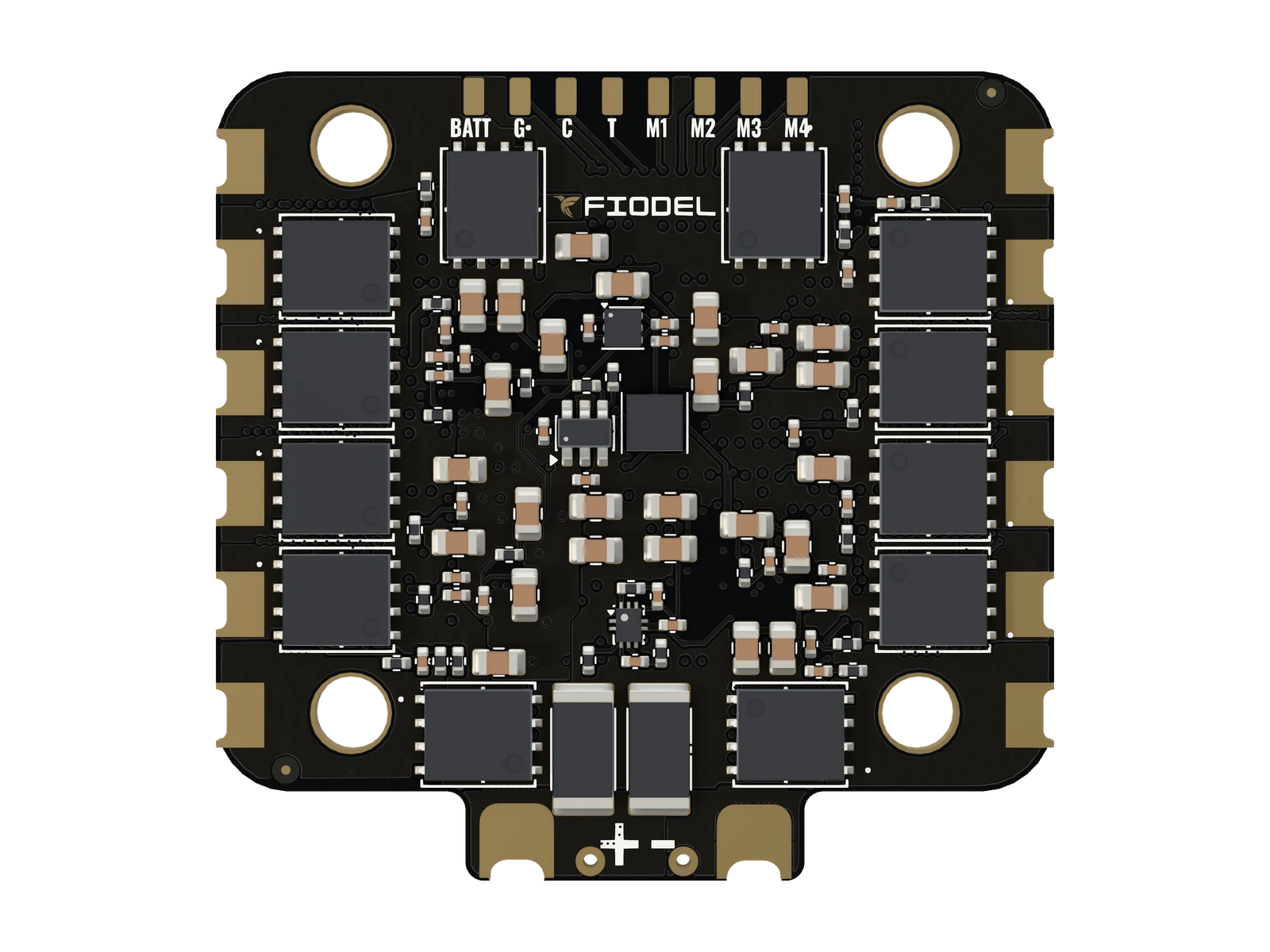
Solder the supplied 470 µF capacitor across the battery pads before the ESC is ever powered, and the XT60 lead to the same pads. They are castellated: they take solder from the top and from the bottom.
CarefulDo not power the ESC without the capacitor fitted.
02Motors
Each motor has three castellated pads on the side edges of the board. The order of the three wires only sets the direction: swap any two to reverse a motor, or reverse it in AM32.
CarefulThe FET pads sit close to the motor pads. Use a fine tip and check for solder bridges before connecting a battery.
03Flight controller
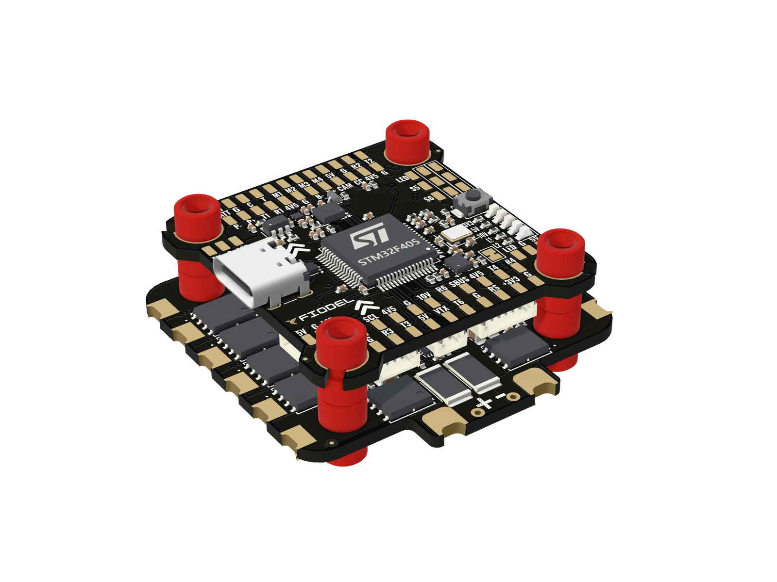
The 60 mm 10-pin cable goes to the flight controller's ESC socket; the same signals are on a row of solder pads. The ESC has no 5 V output: it passes battery voltage to the flight controller, which makes its own rails.
04Betaflight
Set the ESC protocol to DShot; bidirectional DShot is supported. Set the current-sensor scale for 10 mV/A, which in Betaflight is a current scale of 100.
For ESC telemetry, set the flight controller's telemetry UART to Sensor input: ESC — UART5 on the Fiodel F405.
05AM32
The ESC runs AM32 on all four controllers. Settings are changed through the flight controller with any AM32 configurator, with a battery connected and the propellers off.
Leave the current limit inside AM32 switched off: current is measured once for the whole board, not per motor.
06First power
Propellers off. If you have a current-limited supply or a smoke stopper, use it for the first connection. Then spin each motor from Betaflight's Motors tab and check its position and direction.
Stuck, or something here does not match your board? Ask us on WhatsApp.